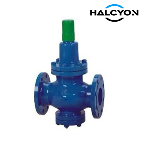
CBM 1079 Water Pressure Reducing Valve 20K
Item | Description |
|---|---|
Product Name | CBM 1079 Water Pressure Reducing Valve 20K |
Certificates | ABS, LR, BV, DNV, RINA, CCS |
FOB Price | Get Latest Price Now |
Warranty | 12 months (unless otherwise specified) |
Place of Origin | China |
Overview
1.1 BASIC PARAMETERS
TABLE 1
| Nominal Diameter Dg (mm) | Flow Rate Q (m³/h) | Initial Pressure P1 (kgf/cm²) | Reduced Pressure P2 (kgf/cm²) |
|---|---|---|---|
| 32 | 19 | 8 ~ 16 | 2 ~ 8 |
| 40 | 30 | 8 ~ 16 | 2 ~ 8 |
| 50 | 47 | 8 ~ 16 | 2 ~ 8 |
| 65 | 80 | 8 ~ 16 | 2 ~ 8 |
| 80 | 120 | 8 ~ 16 | 2 ~ 8 |
1.2 MAIN DIMENSIONS
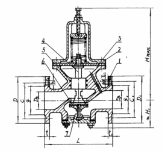
(Dimensions shown in Figure 1 and Table 2)
Figure 1 Parts List: 1 Body, 2 Upper Bonnet, 3 Disc, 4 Stem, 5 Sealing Ring, 6 Lower Disc, 7 Lower Bonnet
TABLE 2 (Unit: mm)
| Nominal Diameter Dg | Structural Dimensions | Inlet Flange | Bolts | Outlet Flange | ||||||||||||||
|---|---|---|---|---|---|---|---|---|---|---|---|---|---|---|---|---|---|---|
| L | Hmax | H1 | D | C | g | h | t | Quantity n | Thread dia. | D1 | C1 | g1 | h1 | t1 | Quantity n | Thread dia. | Weight(Kg) | |
| 32 | 210 | 320 | 72 | 135 | 100 | 80 | 19 | 16 | 4 | M16 | 135 | 100 | 80 | 19 | 16 | 4 | M16 | 12.2 |
| 40 | 220 | 325 | 79 | 140 | 105 | 85 | 19 | 16 | 4 | M16 | 140 | 105 | 85 | 19 | 16 | 4 | M16 | 14.1 |
| 50 | 260 | 370 | 87 | 155 | 120 | 100 | 19 | 16 | 8 | M16 | 155 | 120 | 100 | 19 | 16 | 4 | M16 | 19.1 |
| 65 | 270 | 420 | 93 | 175 | 140 | 120 | 19 | 18 | 8 | M16 | 175 | 140 | 120 | 19 | 18 | 4 | M16 | 26.8 |
| 80 | 280 | 465 | 110 | 200 | 160 | 135 | 23 | 20 | 8 | M20 | 185 | 150 | 130 | 19 | 18 | 8 | M16 | 31.4 |
Marking Example:
Water pressure reducing valve with nominal diameter Dg 32, initial pressure P1 8~16, reduced pressure P2 2~8:
Reducing Valve 8-16/2-8-32 CBM1079-81
2. TECHNICAL REQUIREMENTS
2.1 MATERIALS FOR MAIN PARTS
TABLE 3
| Part Name | Material Name | Material Grade | Standard No. |
|---|---|---|---|
| Body | Tin Bronze | ZQSn10-2 | CB883-78 |
| Lower Bonnet | Tin Bronze | ZQSn10-2 | CB883-78 |
| Disc | Tin Brass | HSn62-1 | YB457-71 |
| Stem | Aluminum Bronze | QAl 9-2 | YB458-71 |
| Upper Bonnet | Cast Steel | ZG 25-II | CB772-70 |
| Sealing Ring | Medium-hard acid and oil resistant rubber | - | - |
| Gasket | Rubber | - | - |
2.2 STRENGTH TEST
The valve body shall be subjected to a hydraulic pressure test of P3 = 24 kgf/cm² for strength and tightness. During the pressure holding period of 5 minutes, if there is no visible deformation or leakage, it is deemed qualified.
2.3 TESTS
After the product is assembled, sealing test and pressure reducing performance test shall be conducted. The test methods shall be in accordance with Clause 3.
2.4 FLANGE
The flange connection dimensions shall be in accordance with CBM1020-81.
2.5 ACCESSORIES
Each product should be provided with the following accessories: 1 adjusting spring, 1 diaphragm, 4 spare bolts. If the user requires additional parts and components, they shall be specified when placing the order.
3. ACCEPTANCE RULES AND TEST METHODS
3.1 ACCEPTANCE
The product shall be inspected and accepted by the factory quality inspection department, and a factory certificate shall be issued.
3.2 SAMPLING
The product shall be delivered in batches. For sampling, the valve size, batch size, items for sampling, and the test methods and acceptance rules shall be specified in the contract at the time of ordering.
3.3 SEALING AND PRESSURE REDUCING PERFORMANCE TESTS
These tests shall be carried out in accordance with the installation line diagram shown in Figure 2.
3.3.1 Sealing Test: The adjusting spring shall be fully relaxed, and stop valve ④ shall be closed. Then stop valves ② and ⑤ shall be opened, and water pump ① shall be started. The inlet pressure shall be adjusted to 16 kgf/cm², and its value shall be read from pressure gauge ③. The pressure rise on the reduced pressure side shall not exceed 1.6 kgf/cm².
TABLE 4
| Nominal Diameter Dg (mm) | 32 | 40 | 50 | 65 | 80 |
|---|---|---|---|---|---|
| δ = ΔP2 / P2 × 100% ≤ | 7 | 9 | 14 | 17 | 22 |
| Note: ΔP2 is the drop value indicated on pressure gauge ⑥ when the valve is fully closed. ΔP2 = P2 (Q=0) - P2 (Q=max). | |||||
Related Products:
GB T/1852 Marine Flanged Cast Steel Steam Pressure Reducing Valve
CB/T3656 Marine Air Pressure Reducing Valve
DRAWING