Marine Cast Iron Sight Glass
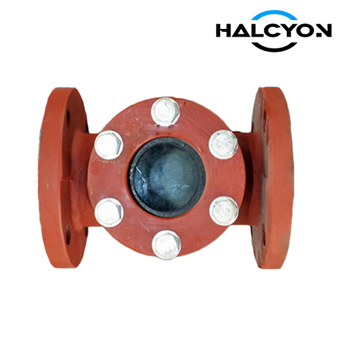
The Marine Cast Iron Sight Glass is a robust inline visual inspection device engineered for shipboard piping systems. It allows operators to directly observe fluid flow, color, clarity, and the presence of condensate or contaminants without disrupting operations. Built from heavy-duty cast iron and high-transparency safety glass, it is designed to withstand the harsh vibration, corrosion, and temperature fluctuations typical of marine environments. Recognized as an essential monitoring component often integrated with valve assemblies, this sight glass delivers reliable, long-lasting performance backed by international marine standards.
Overview
1. Design Standards & Certifications
Standard Compliance: Manufactured in strict accordance with JIS F 7201 (5K) and JIS F 7202 (10K) – the dedicated Japanese Industrial Standards for marine cast iron sight glasses.
Material Norms: Cast iron body meets ASTM A126 Class B (or equivalent) for superior castability and strength. Nodular cast iron options available on request.
Glass Standard: Viewing disc made of clear, tempered borosilicate glass conforming to ISO 3585, offering high thermal shock resistance and mechanical strength.
Classification Society Approval: Type approval certificates from major classification societies (e.g., DNV, ABS, LR, NK, BV) can be provided upon order, ensuring full regulatory acceptance.
2. Construction & Superior Materials
Body: Fine-grain cast iron, cast in a streamlined flow path to minimize turbulence. Coated with a marine-grade high-build epoxy system (minimum 250 µm DFT) compliant with ISO 12944-5 (C5-M) for extreme corrosion protection.
Viewing Disc: High-polished borosilicate glass, selected for excellent transparency and resistance to thermal shock up to 150°C. Optionally fitted with a protective guard frame or safety film.
Sealing: Chemical-resistant gaskets in PTFE or non-asbestos aramid fiber, compatible with seawater, fuel oils, lubricants, and steam.
Fasteners: All bolting in AISI 316 stainless steel, ensuring long-term corrosion resistance even in salty air.
3. Performance Features
Fail-Safe Visibility: Clear, wide-angle view port allows instant flow verification of cooling water, bilge, ballast, and oil circuits.
Marine-Tough Design: Anti-vibration structure with robust wall thickness; resistant to shock loads and hull flexing.
Safety-First: The glass disc is seated in a precision-machined recess with controlled gasket compression, preventing stress cracks. Guarded sight glasses are available for high-pressure services.
Wide Service Range: Standard ratings JIS 5K/10K, with working pressures up to 1.0 MPa (10 bar) and continuous temperatures from -10°C to 120°C (higher on request).
Easy Maintenance: Simple through-body design allows quick glass replacement without removing the entire assembly from the line.
4. Typical Marine Applications
Cooling Systems: Monitoring seawater and freshwater circulation.
Bilge & Ballast Lines: Confirming flow or empty-pipe condition before pump start-up.
Fuel Oil & Lube Oil Service: Checking oil clarity, water contamination, and steady supply to engines.
Fire-Fighting & Foam Systems: Visual confirmation of extinguishing agent flow.
Steam Condensate Lines: Detecting flash steam and condensate return status.
5. Quality Control & Testing
Each sight glass undergoes a hydrostatic shell test at 1.5× design pressure, in strict accordance with JIS F 7201 requirements.
100% dimensional inspection, visual examination for casting soundness, and glass flatness check.
Full material traceability is maintained, with EN 10204 Type 3.1 mill certificates available for body, glass, and gaskets.
Optional non-destructive testing (dye penetrant) for critical high-pressure orders.