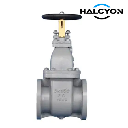
JIS F7363 Gate Valve Cast Iron 5K
Item | Description |
|---|---|
Product Name | JIS F7363 Gate Valve Cast Iron 5K |
Certificates | ABS, LR, BV, DNV, RINA, CCS |
FOB Price | Get Latest Price Now |
Warranty | 12 months (unless otherwise specified) |
Place of Origin | China |
Overview
1. SCOPE
This standard specifies cast iron 5K gate valves (hereinafter referred to as "gate valves") used for ship's steam piping, fuel oil piping, lubricating oil piping, fresh water piping, and feed water piping.
2. RELATIONSHIP BETWEEN FLUID CONDITION AND MAXIMUM WORKING PRESSURE
The relationship between the fluid condition and the maximum working pressure for gate valves shall be as shown in Table 1.
TABLE 1
| Fluid Condition | Maximum Working Pressure (MPa) | ||
|---|---|---|---|
| Nominal Size 200 or less | Nominal Size 250~400 | Nominal Size 450~600 | |
| Saturated Steam | 0.3 | 0.2 | - |
| Air, Gas, Oil, and Pulsating Water | 0.5 | 0.5 | 0.5 |
| Static Water below 120°C | 0.7 | 0.7 | 0.5 |
3. CONSTRUCTION, SHAPE, AND DIMENSIONS
The construction, shape, and dimensions of gate valves shall be as shown in Fig. 1 and Fig. 3. Furthermore, appropriate ribs shall be added to the body, bonnet, and disc as necessary. The tolerance for body wall thickness (a) and bonnet wall thickness (a1) shall, in principle, be +15% / -10%. However, if the calculated tolerance value is less than 1mm, the tolerance shall be 1mm.
Note: For nominal sizes 450~600, when the working pressure is 0.2MPa or less, the thrust ball bearing may be omitted, and the valve stem may be directly connected to the handwheel in a structure where the handwheel is closed by direct rotation.
4. MATERIALS
The materials for gate valves shall be as follows:
(1) The body, bonnet, main parts (disc, seat, stem), and nuts shall be as shown in Fig. 2 and Fig. 4. Furthermore, B Series and S Series are distinguished by the material combination.
(2) Other materials shall, in principle, be as shown in Fig. 2 and Fig. 4.
5. INSPECTION
The inspection of gate valves shall be carried out in accordance with JIS F 7400, performing the following tests (1) to (5):
(1) Material inspection
(2) External appearance inspection
(3) Dimensional inspection
(4) Assembly inspection
(5) Pressure test. The pressure test shall be performed at the test pressures shown in Table 2. However, for the seat water leakage test of nominal size 300 or more, the inspector may specify a pressure lower than that shown in Table 2.
TABLE 2
| Nominal Size | Test Pressure (MPa) | |
|---|---|---|
| Seat Water Leakage | Body Water Pressure | |
| 400 or less | 0.77 | 1.05 |
| 450~600 | 0.55 | 0.75 |
6. DESIGNATION
The designation of gate valves shall be in accordance with the name, or its abbreviation, or the standard number, along with the nominal size and material series designation.
Example 1. For nominal size 50, material B series:
Shipbuilding Cast Iron 5K Gate Valve B or FS 5050 B or JIS F 7363-50B
(Note: FS indicates Shipbuilding Cast Iron Gate Valve; 50 indicates nominal pressure; 50 indicates nominal size; B indicates material B series.)
Example 2. For nominal size 450, material S series (with thrust ball bearing):
Shipbuilding Cast Iron 5K Gate Valve S (with thrust ball bearing) or FS 5450 ST or JIS F 7363-450ST
(Note: ST indicates thrust ball bearing, S indicates material S series.)
7. MARKING
(1) The following items shall be marked on the surface of the body:
Example: 5K-50
(2) Seat water leakage test pressure (Only for nominal size 300 or more, when inspection pressure is specified by the purchaser)
(3) Manufacturer's name or its abbreviation
(4) Year of manufacture or its lot number
FIG. 1 DIMENSIONS TABLE FOR NOMINAL SIZE 50~400 (UNIT: MM)
| Nominal Size | d | L | D | Flange C | No. of Bolt Holes | Bolt Diameter | t | H | L | Handwheel D2 | d1 | a | a1 | H1 | B1 | B2 | B3 | B4 | No. of Bolts | Bolt Diameter | d4 | d5 | S | d6 | Calculated Mass (kg) | |
|---|---|---|---|---|---|---|---|---|---|---|---|---|---|---|---|---|---|---|---|---|---|---|---|---|---|---|
| 50 | 50 | 180 | 130 | 105 | 4 | 15 | M12 | 16 | 285 | 58 | 125 | 8 | 7 | 75 | 28 | 94 | 140 | 153 | - | 6 | M12 | TW16 | 16 | 10 | 26 | 13.5 |
| 65 | 65 | 190 | 155 | 130 | 4 | 15 | M12 | 18 | 330 | 74 | 140 | 9 | 8 | 85 | 118 | 145 | 172 | - | - | 6 | M12 | TW18 | 18 | 12 | 28 | 19.0 |
| 80 | 80 | 200 | 180 | 145 | 4 | 19 | M16 | 18 | 380 | 89 | 160 | 9 | 8 | 95 | 140 | 155 | 195 | - | - | 8 | M12 | TW20 | 20 | 14 | 32 | 24.2 |
| 100 | 100 | 230 | 200 | 165 | 8 | 19 | M16 | 20 | 430 | 109 | 180 | 10 | 9 | 110 | 130 | 143 | 178 | 230 | - | 8 | M16 | TW22 | 22 | 14 | 36 | 35.3 |
| 125 | 125 | 250 | 235 | 200 | 8 | 19 | M16 | 20 | 495 | 135 | 200 | 11 | 10 | 145 | 177 | 195 | 265 | - | - | 8 | M16 | TW24 | 24 | 17 | 38 | 48.1 |
| 150 | 150 | 270 | 265 | 230 | 8 | 19 | M16 | 22 | 560 | 159 | 224 | 12 | 11 | 165 | 200 | 205 | 290 | - | - | 8 | M16 | TW26 | 26 | 19 | 42 | 63.3 |
| 200 | 200 | 290 | 320 | 280 | 8 | 23 | M20 | 24 | 680 | 211 | 280 | 14 | 13 | 210 | 249 | 265 | 360 | - | - | 8 | M20 | TW30 | 30 | 22 | 48 | 103 |
| 250 | 250 | 330 | 385 | 345 | 12 | 23 | M20 | 26 | 800 | 262 | 355 | 15 | 15 | 245 | 308 | 270 | 438 | - | - | 12 | M20 | TW34 | 34 | 27 | 54 | 164 |
| 300 | 300 | 370 | 430 | 390 | 12 | 23 | M20 | 28 | 920 | 312 | 400 | 18 | 16 | 275 | 374 | 310 | 520 | - | - | 12 | M20 | TW38 | 38 | 30 | 60 | 236 |
| 350 | 350 | 410 | 480 | 435 | 12 | 25 | M22 | 30 | 1000 | 350 | 450 | 19 | 17 | 300 | 412 | 340 | 580 | - | - | 12 | M22 | TW40 | 40 | 30 | 62 | 307 |
| 400 | 400 | 370 | 540 | 495 | 16 | 25 | M22 | 30 | 1100 | 394 | 500 | 21 | 18 | 330 | 466 | 360 | 640 | 680 | 14 | 16 | M22 | TW44 | 44 | 32 | 68 | 405 |
Remark 1: Flanges shall conform to JIS B 2210 nominal pressure 5K.
Remark 2: Threads for d4 shall conform to JIS B 0222; Threads for d5 shall conform to JIS B 0205.
Remark 3: The direction of the opening/closing indicator plate shall, in principle, face the marking side of the body.
Remark 4: The stem may be changed to a structure with a driving pin for opening/closing.
Remark 5: Nameplate is optional per purchaser requirements.
Remark 6: Calculated mass shows the values for B Series materials.
FIG. 2 MATERIALS TABLE FOR NOMINAL SIZE 50~400
| Part No. | Part Name | Material (B Series) | Material (S Series) |
|---|---|---|---|
| 1 | Body | JIS G 5501 FC200 | JIS G 5501 FC200 |
| 2 | Bonnet | JIS G 5501 FC200 | JIS G 5501 FC200 |
| 3 | Packing Box | JIS G 5501 FC200 | JIS G 5501 FC200 |
| 4 | Disc | JIS G 5501 FC200 | JIS G 5501 FC200 |
| 5 | Handwheel | JIS G 5501 FC200 | JIS G 5501 FC200 |
| 6 | Seat Ring | JIS H 5111 BC6 | JIS G 4303 SUS420J1 or SUS420J2 |
| 7 | Disc Seat | JIS H 5111 BC6 | JIS G 4303 SUS420J1 or SUS420J2 |
| 8 | Stem | JIS H 5111 BC6 | JIS G 4303 SUS403 |
| 9 | Stem Nut | JIS H 5111 BC6 | JIS G 4303 SUS403 |
| 10 | Stem | JIS H 5111 BC6 | JIS G 4303 SUS403 |
| 11 | Packing Gland | - | - |
| 12 | Indicator Plate | JIS H 3100 C2801P | JIS H 3100 C2801P |
| 13 | Indicator Plate Holder | - | - |
| 14 | Stem | JIS H 3250 C3771BD or C3771BE | JIS G 4303 SUS403 |
| 15 | Stud Bolt | JIS G 3101 SS400 | JIS G 3101 SS400 |
| 16 | Hexagon Nut | JIS G 3101 SS400 | JIS G 3101 SS400 |
| 17 | Stud Bolt | JIS G 3101 SS400 | JIS G 3101 SS400 |
| 18 | Stud Bolt | JIS H 3250 C3771BD | JIS H 3250 C3771BD |
| 19 | Stem Pin | JIS G 4303 SUS403 | JIS G 4303 SUS403 |
| 20 | Hexagon Nut | JIS G 3101 SS400 | JIS G 3101 SS400 |
| 21 | Hexagon Nut | - | - |
| 22 | Hexagon Nut | JIS H 3250 C3604BD | JIS H 3250 C3604BD |
| 23 | Hexagon Nut | - | - |
| 24 | Cross-recessed Pan Head Screw | JIS H 3260 C2700W | JIS H 3260 C2700W |
| 25 | Split Pin | JIS H 3260 C2600W | JIS H 3260 C2600W |
| 26 | Packing | Per JIS F 7102 | Per JIS F 7102 |
| 27 | Gasket | Per JIS F 7102 | Per JIS F 7102 |
| 28 | Gasket | Per JIS F 7102 | Per JIS F 7102 |
| 29 | Name Plate | JIS H 3100 C2801P | JIS H 3100 C2801P |