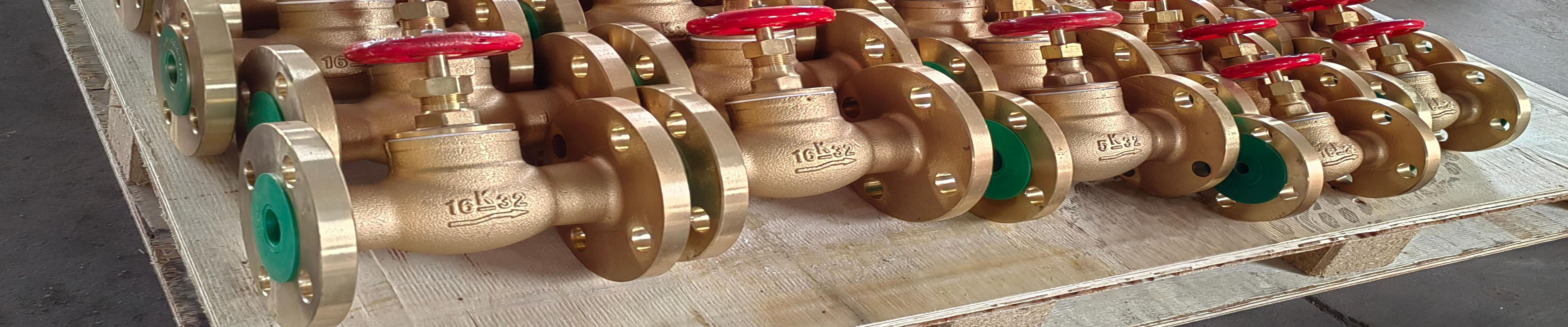
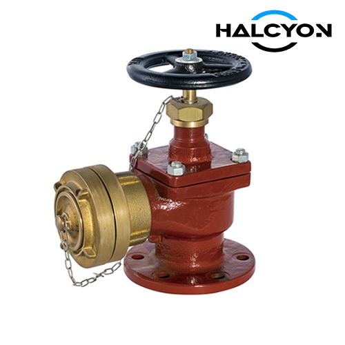
GB/T2032-2018 Marine Flanged Fire Hydrant Type AS/BS
Item | Description |
|---|---|
Product Name | GB/T2032-2018 Marine Flanged Fire Hydrant Type AS/BS |
Certificates | ABS, LR, BV, DNV, RINA, CCS |
FOB Price | Get Latest Price Now |
Warranty | 12 months (unless otherwise specified) |
Place of Origin | China |
Overview
1. SCOPE
This standard specifies the classification, marking, requirements, test methods, inspection rules, marking, packaging, and storage of marine flanged fire hydrants (hereinafter referred to as "fire hydrants") with flange connection dimensions and sealing surfaces in accordance with GB/T 2501 and CB/T 4196.
This standard is applicable to the design, manufacture, and acceptance of fire hydrants used in fresh water and seawater piping systems.
2. NORMATIVE REFERENCES
The provisions of the following documents become provisions of this standard through reference in this standard. For dated references, subsequent amendments (excluding errata) or revisions do not apply to this standard. However, parties agreeing to this standard are encouraged to investigate whether the latest editions of the following documents apply. For undated references, the latest edition applies to this standard.
GB/T 600-2008 - General technical requirements for ship piping valves
GB/T 1176-2013 - Casting copper and copper alloys
GB/T 1184-1996 - Geometrical tolerances - Unindicated tolerance values
GB/T 1220-2007 - Stainless steel bars
GB/T 1804-2000 - General tolerances - Tolerances for linear and angular dimensions without individual tolerance indications
GB/T 1958 - Geometrical product specifications (GPS) - Geometrical tolerance verification
GB/T 2031-2018 - Marine fire hose couplings
GB/T 2501 - Ship flanges - Connection dimensions and sealing faces
GB/T 5231-2012 - Wrought copper and copper alloy grades and chemical composition
GB/T 5574-2008 - Industrial rubber sheets
GB/T 16253-1996 - Steel castings for pressure purposes
CB/T 3927 - Wall thickness of ship casting valves
CB/T 4196 - Ship flanges - Connection dimensions and sealing faces
3. CLASSIFICATION AND MARKING
3.1 TYPES
Types of fire hydrants are specified as follows:
AS TYPE - Straight-through fire hydrant with flange connection dimensions per GB/T 2501.
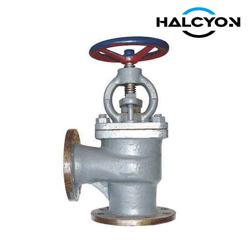
BS TYPE - Right-angle fire hydrant with flange connection dimensions per GB/T 2501.
3.2 BASIC PARAMETERS
The basic parameters of fire hydrants are shown in Table 1.
TABLE 1 - BASIC PARAMETERS OF FIRE HYDRANTS
| TYPE | NOMINAL PRESSURE PN | WORKING PRESSURE P MPa | NOMINAL SIZE DN |
|---|---|---|---|
| AS | 16 | 1.6 | 40, 50, 65 |
| BS | 16 | 1.6 | 40, 50, 65 |
3.3 STRUCTURE AND DIMENSIONS
3.3.1 The structure and basic dimensions of Type AS and Type BS fire hydrants with nominal pressure PN16 are shown in Figure 1 and Table 2.
TABLE 2 - BASIC DIMENSIONS OF TYPE AS AND BS FIRE HYDRANTS (UNIT: MM)
| NOMINAL SIZE DN | OVERALL DIMENSIONS | BODY WALL THICKNESS t | FLANGE CONNECTION DIMENSIONS | HANDWHEEL D3 | LIFT m | COUPLING d0 | THEORETICAL MASS / kg | |||||||||
|---|---|---|---|---|---|---|---|---|---|---|---|---|---|---|---|---|
| L | H | H1 | D | D1 | D2 | b | d0 | n | Th. | TYPE AS (Brass) | TYPE BS (Stainless Steel) | |||||
| 40 | 240 | 134 | 70 | 167 | 140 | 90 | 110 | 88 | 16 | 4 | M16 | 120 | 11 | 14 | 7.25 | 6.58 |
| 50 | 258 | 143 | 80 | 170 | 160 | 125 | 125 | 102 | 18 | 4 | M16 | 120 | 14 | 16 | 8.94 | 8.11 |
| 65 | 294 | 170 | 100 | 186 | 180 | 145 | 145 | 122 | 18 | 4 | M16 | 140 | 20 | 20 | 10.71 | 9.34 |
3.4 MARKING
3.4.1 PRODUCT MARKING
The product marking method for fire hydrants is as follows:
[ TYPE ] [ Nominal pressure or 10 times working pressure value ] [ Nominal size value, padded with "0" if less than 3 digits ] [ Material code: Brass (Q), Yellow Brass (H), Stainless Steel (N) ] [ PN16 fire hydrant sealing code: Soft sealing (R), Hard sealing (Y) ]
3.4.2 MARKING EXAMPLES
The marking of fire hydrants consists of the product name, applicable standard number, and product type.
Example:
Nominal pressure PN16, nominal size DN65, sealing surface hard sealing, flange connection dimensions and sealing surfaces in accordance with GB/T 2501, right-angle brass fire hydrant is marked as:
FIRE HYDRANT GB/T 2032-2018 BS1665HY
4. REQUIREMENTS
4.1 MATERIALS
4.1.1 The materials for main parts of fire hydrants are shown in Table 5.
TABLE 5 - MATERIALS FOR MAIN PARTS OF FIRE HYDRANTS
| PART NAME | MATERIAL NAME | GRADE | STANDARD NO. | |
|---|---|---|---|---|
| BODY, BONNET, DISC | CAST TIN BRONZE OR CAST TIN ZINC BRONZE | ZCuSn10Zn2 or ZCuZn16Si4 | GB/T 1176-2013 | |
| STAINLESS STEEL | ZG07Cr19Ni11Mo2 | GB/T 16253-1996 | ||
| STEM | ALUMINUM BRONZE | QA19-2 | GB/T 5231-2012 | |
| STAINLESS STEEL | 06Cr17Ni14Mo2 | GB/T 1220-2007 | ||
| FIRE HOSE COUPLING, COVER | CAST TIN ZINC BRONZE | ZCuZn16Si4 | GB/T 1176-2013 | |
| SEALING SURFACE | METAL | SAME AS BODY, BONNET MATERIAL | - | |
| NON-METAL | INDUSTRIAL RUBBER SHEET | C-05-4-H6 | GB/T 5574-2008 |
4.1.2 Each furnace of castings shall be provided with at least 3 spare test bars with furnace numbers, and the retention period shall be no less than 3 years.
4.2 DIMENSIONAL TOLERANCES
4.2.1 The wall thickness of the fire hydrant shall comply with the requirements of CB/T 3927.
4.2.2 The unindicated linear dimensional tolerances of the fire hydrant shall comply with the requirements of Grade m in GB/T 1804-2000.
4.3 FORM AND POSITION TOLERANCES
The unindicated form and position tolerances of the fire hydrant shall comply with the requirements of Grade K in GB/T 1184-1996.
4.4 APPEARANCE
The appearance of the fire hydrant shall comply with the requirements of Clause 3.10 in GB/T 600-2008.
4.5 STRENGTH
The body of the fire hydrant shall have no leakage under a hydraulic pressure of 1.5 times the working pressure.
4.6 SEALING
4.6.1 The disc sealing surface of the fire hydrant shall have no leakage under a hydraulic pressure of 1.1 times the working pressure.
4.6.2 The sealing surface of the stem and bonnet packing of the fire hydrant shall allow a leakage rate of (0.01 × DN) mm³/s under a hydraulic pressure of 1.1 times the working pressure.
4.7 INTERFACE
4.7.1 The fire hose coupling of the fire hydrant shall comply with Type A of GB/T 2031-2018.
4.7.2 The cover of the fire hydrant shall comply with Type C of GB/T 2031-2018.
4.8 MASS
The positive deviation of the mass of the fire hydrant shall not exceed 4% of the theoretical mass.
5. TEST METHODS
5.1 MATERIALS
The chemical composition and mechanical properties of fire hydrant castings shall be tested according to the methods specified in GB/T 1176-2013 or GB/T 16253-1996. Other materials of the fire hydrant shall be tested by inspecting the material grade and quality certificate. The results shall comply with the requirements of 4.1.
5.2 DIMENSIONAL TOLERANCES
5.2.1 The wall thickness of the fire hydrant shall be inspected using a thickness gauge, vernier caliper, steel ruler, caliper, and other measuring tools. The results shall comply with the requirements of 3.3 and 4.2.1.
5.2.2 The unindicated linear dimensional tolerances of the fire hydrant shall be inspected using gauges of corresponding grades. The results shall comply with the requirements of 3.3 and 4.2.2.
5.3 FORM AND POSITION TOLERANCES
The form and position tolerances of the fire hydrant shall be inspected according to the methods specified in GB/T 1958. The results shall comply with the requirements of 4.3.
5.4 APPEARANCE
The appearance of the fire hydrant shall be inspected visually. The results shall comply with the requirements of 4.4.
5.5 STRENGTH
The strength test of the fire hydrant shall be carried out according to the methods specified in Clause 4.12 of GB/T 600-2008. The results shall comply with the requirements of 4.5.
5.6 SEALING
The sealing test of the fire hydrant shall be carried out according to the methods specified in Clause 4.13 of GB/T 600-2008. The results shall comply with the requirements of 4.6.1 and 4.6.2.
5.7 INTERFACE
The interface of the fire hydrant shall be inspected visually and by checking the product marking and certificate. The results shall comply with the requirements of 4.7.
5.8 MASS
Place the fire hydrant on a scale with a division value no greater than 0.1 kg for weighing. The results shall comply with the requirements of 4.8.