GB/T 40515-2021 MARINE CRYOGENIC GLOBE VALVES
Item | Description |
|---|---|
Product Name | GB/T 40515-2021 MARINE CRYOGENIC GLOBE VALVES |
Certificates | ABS, LR, BV, DNV, RINA, CCS |
FOB Price | Get Latest Price Now |
Warranty | 12 months (unless otherwise specified) |
Place of Origin | China |
Overview
1. PRESSURE-TEMPERATURE RATINGS
TABLE 1 - MEDIA TYPES (EXAMPLES)
| MEDIA TYPE | TEMPERATURE (BAR) / °C | LIQUID DENSITY / (kg/m³) |
|---|---|---|
| LNG (Liquefied Natural Gas) | -165 ~ -80 | 430 ~ 470 |
| NG (Natural Gas) | -160 ~ -65 | 0.7 ~ 0.89 |
| LN2 (Liquid Nitrogen) | -196 | 801 |
| N2 (Nitrogen) | -196 ~ -65 | 4.188 |
TABLE 2 - WORKING PRESSURE AND DESIGN TEMPERATURE
| PN (Class) | MAXIMUM WORKING PRESSURE MPa (Psi) | REMARKS |
|---|---|---|
| 20 (150) | 2.0 (290) | Ambient Temperature |
| 50 (300) | 5.2 (750) | Ambient Temperature |
| 100 (600) | 10.3 (1500) | Ambient Temperature |
| 150 (900) | 13.8 (2000) | Ambient Temperature |
| 250 (1500) | 15.5 (2250) | Ambient Temperature |
Note: Pressure ratings correspond to ASME B16.34. Design temperature shall be between -196°C and 100°C. When the pressure class exceeds PN150 (Class900), it may be agreed upon by both parties. Working pressure depends on the purchaser's piping system.
2. CONSTRUCTION AND DESIGN
2.1 BASIC STRUCTURE
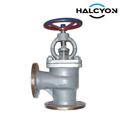
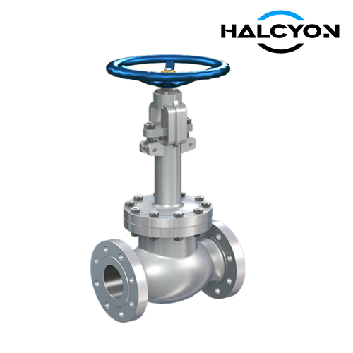
The globe valve is typically an Outside Screw and Yoke (OS&Y) type with a bolted bonnet. The structure and function shall be as specified. If a different structure is used, the manufacturer and purchaser must reach an agreement.
2.2 BODY
Type: Straight-through type.
Material: Cast or forged materials with performance not lower than those specified in Table 3.
Manufacturing:
Valve body structural length shall comply with ASME B16.10.
Minimum body wall thickness shall comply with ASME B16.34.
Butt-welding ends: Shall comply with ASME B16.25 or BS 1873.
Flanged ends: PN20 and PN50 (Class150 & Class300) shall use raised face (RF) flanges; PN100 (Class600) and above shall use large tongue (LGF) flanges or raised face (RF) flanges, complying with ASME B16.5 and ASME B16.47.
2.3 EXTENDED BONNET
Design: The minimum wall thickness of the bonnet shall meet ASME B16.34. The extension length must ensure the packing is away from the cryogenic zone. An isolation sleeve and drip plate may be installed on the extension. Vent holes should be designed to prevent ice blockage.
Material:
Castings: ASTM A351 CF3, CF3M.
Forgings: ASTM A182 F304L, F316L.
Pipe/Connections: ASTM A312 or equivalent A358 304L/316L. Seamless pipes are required (welded pipes are not allowed).
2.4 DISC
Design: Single-piece disc located at the throttling flow port. When the temperature range is -80°C to -52°C, a soft-seated seal ring may be used. The disc guide shall align with the valve seat. No separate seat sealing ring is required if the body has an integral seat.
Material: ASTM A182 F304 or F316 or better. To improve wear resistance, a hard alloy overlay of at least 1.6 mm thickness shall be deposited on the sealing surface after finishing.
2.5 STEM
Design: Extended stem type. Minimum diameter shall comply with BS 1873. The stem shall have sufficient strength and not separate from the disc under working pressure. The stem surface in contact with packing must be precision-finished to 0.8 μm to prevent leakage. The connection with the disc shall be T-slot or spherical. Threads shall comply with ASME B1.5 or B1.8.
Material: ASTM A182 F316 or better.
2.6 STEM SEALING (PACKING)
The stem shall be sealed with a suitable structure (e.g., packing box, sealing ring) to prevent leakage.
Packing materials shall be graphite, PTFE, or braided PTFE. The packing shall not chemically react with the process fluid.
The packing must be replaceable without removing the valve from the line.
2.7 SEAT SEALING RING
Design: Solid or integral seat ring with a port restricting flow.
Material: ASTM A182 F316 or better. Surface hardening is required for the contact area with the disc. If a soft-seated disc is used, surface hardening of the seat ring is not required. Hardened layer depth shall be at least 1.6 mm.
2.8 BOLTS AND NUTS
Used for bonnet flange, yoke, and packing gland. Shall comply with BS 1873.
Bolts: ASTM A320 B8 Class 2 (minimum).
Nuts: ASTM A194 (minimum).
2.9 OPERATION AND ACTUATOR
Drive modes include handwheel (for low pressure), gearbox (for high pressure), chain wheel, pneumatic, or electric actuators, as specified by the purchaser.
3. MATERIALS OF MAIN PARTS
TABLE 3 - MATERIALS FOR MANUFACTURING METHODS
| MANUFACTURING METHOD | FLANGED END TYPE | WELDING END TYPE |
|---|---|---|
| Forged | ASTM A182 F304, F316 | ASTM A182 F304L, F316L |
| Cast | ASTM A351 CF8, CF8M | ASTM A351 CF3, CF3M |
4. INQUIRY REQUIREMENTS (FOR BUYERS)
To ensure an accurate quotation and compliance with GB/T 40515-2021 / ISO 18139:2017, please provide the following details:
Product Name: Marine Cryogenic Globe Valve
Standard: GB/T 40515-2021 / ISO 18139:2017
Nominal Diameter (DN): [e.g., 25, 50, 100]
Nominal Pressure (PN/Class): [e.g., PN20 (Class150), PN50 (Class300)]
Working Medium: [e.g., LNG, NG, LN2, N2]
Design Temperature: [e.g., -196°C]
End Connection: [ ] Flanged (RF/LGF) / [ ] Butt-welding
Body Material: [ ] Forged (ASTM A182 F304/F316) / [ ] Cast (ASTM A351 CF8/CF8M)
Operation Type: [ ] Handwheel / [ ] Gearbox / [ ] Pneumatic / [ ] Electric
Classification Society Required: [e.g., NK, LR, DNV, ABS, CCS, or None]
Quantity: [e.g., 10 pcs]
Destination Port: [e.g., Singapore, Rotterdam]
Inspection Requirements: [e.g., EN 10204 3.1 Certificate, Third-Party Witness]