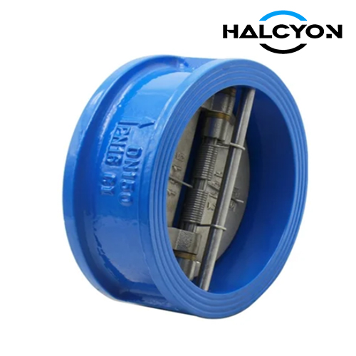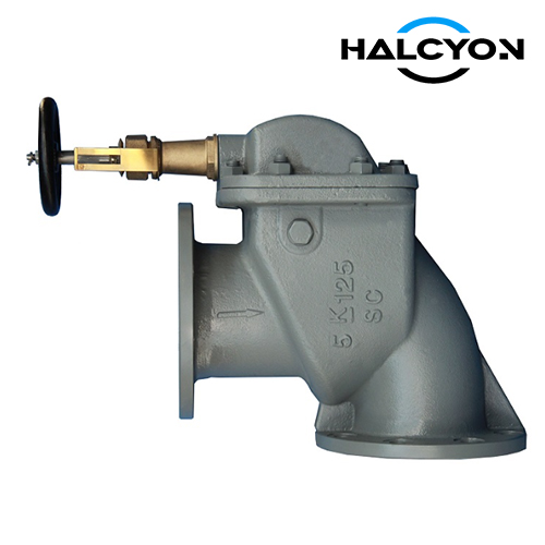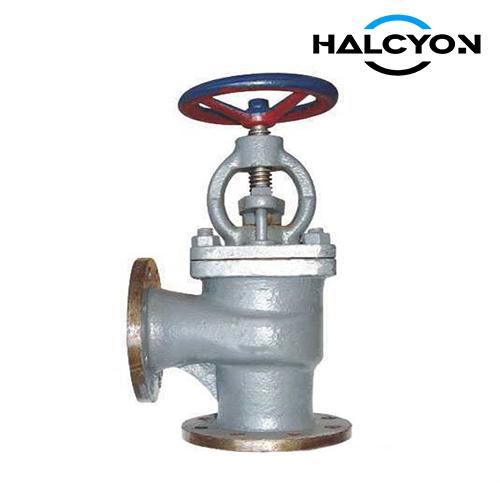
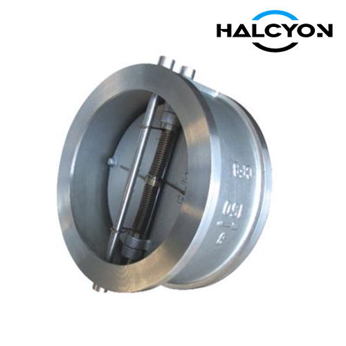
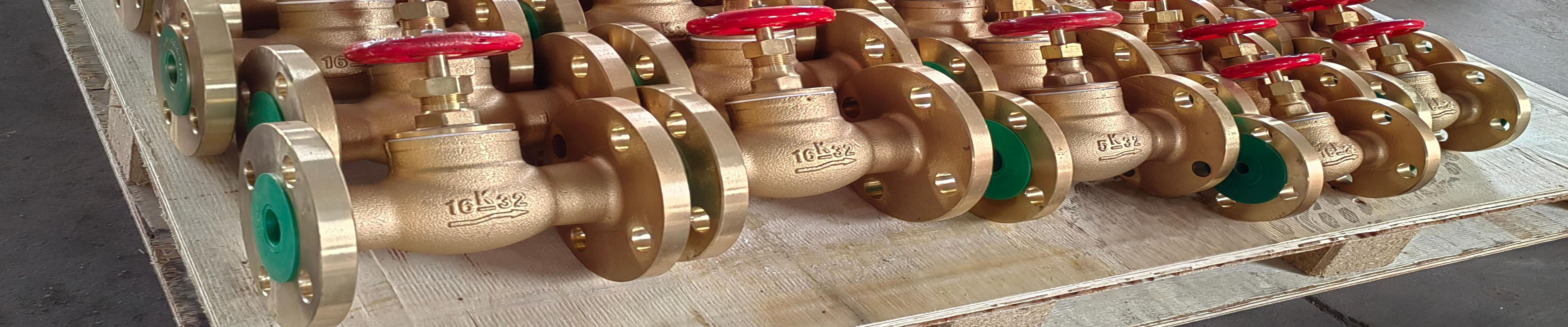
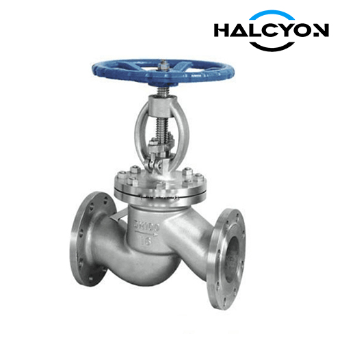
CB/T3942 SUS 304 Globe Valve
Item | Description |
|---|---|
Product Name | CB/T3942 SUS 304 Globe Valve |
Certificates | ABS, LR, BV, DNV, RINA, CCS |
FOB Price | Get Latest Price Now |
Warranty | 12 months (unless otherwise specified) |
Place of Origin | China |
Overview
1. PRODUCT OVERVIEW
The CB/T 3942-2002 Stainless Steel Flanged Stop Valve is a marine-grade globe valve designed for shipboard piping systems carrying corrosive and non-corrosive media. This standard is issued by the National Defense Science and Technology Industry Commission of the People's Republic of China. The valve features a flange connection design and is constructed from high-grade stainless steel (SUS 304 equivalent) for excellent corrosion resistance in harsh marine environments.
This standard applies to stop valves used in piping systems of liquefied gas carriers, bulk chemical carriers, and naval vessels with nominal pressures not exceeding 6.4 MPa and design temperatures not lower than -165°C. Stop valves for corrosive media in other ship piping systems may also refer to this standard.
Key Design Characteristics:
Flanged connection with sealing surface per CB/T 569 or CB/T 2501
Stainless steel construction (SUS 304 / 022Cr19Ni10) for superior corrosion resistance
Straight-through and right-angle configurations available
Manual handwheel operation with reliable shut-off and throttling capability
Suitable for low-temperature service down to -165°C
2. WORKING PRINCIPLE
The globe valve operates through a linear motion mechanism. The stem axis is perpendicular to the seat sealing surface. The valve disc is connected to the stem and moves vertically to open or close the flow passage. When the handwheel is turned, the stem rises or lowers the disc, which engages or disengages with the seat ring.
Key operational features:
Short stroke: The valve stem travel is relatively short, enabling quick opening and closing.
Reliable shut-off: The disc and seat make contact only in the closed position, resulting in minimal mechanical wear on the sealing surfaces.
Throttling capability: The valve is suitable for both isolation and flow regulation applications.
Easy maintenance: The seat and disc sealing elements can be repaired or replaced without removing the entire valve from the pipeline in most configurations.
Flow direction: The flow direction is typically indicated by an arrow on the body. Globe valves can be installed in either direction but are most effective when flow enters from the seat side.
3. DESIGN & MANUFACTURING STANDARDS
| STANDARD | DESCRIPTION |
|---|---|
| CB/T 3942-2002 | Chinese Marine Industry Standard - Stainless Steel Flanged Stop Valves |
| CB/T 569 | Ship flanges - Connection dimensions and sealing faces |
| CB/T 2501 | Ship flanges - Connection dimensions and sealing faces (four-position) |
| API 598 | Valve Inspection and Testing - Shell test at 1.5× CWP, seat test at 1.1× CWP |
| ISO 5208 | Industrial valves – Pressure testing of valves |
| GB/T 1220-1992 | Stainless steel bars |
| GB/T 3280 | Cold rolled stainless steel sheets and plates |
| GB/T 4237 | Hot rolled stainless steel sheets and plates |
Design Standard: CB/T 3942-2002
Testing Standard: API 598 / ISO 5208
4. MATERIALS OF CONSTRUCTION
| PART NAME | MATERIAL | STANDARD |
|---|---|---|
| Body / Bonnet / Disc | Stainless Steel (022Cr19Ni10 / SUS 304 equivalent) | GB/T 3280 / GB/T 4237 |
| Stem / Gland | Stainless Steel (022Cr17Ni12Mo2 / 316L equivalent) | GB/T 1220-1992 |
| Stem / Gland (Alternative) | 0Cr13 (410S) | GB/T 1220-1992 |
| Packing / Gasket | PTFE | — |
| Sealing Surface (PN ≥ 4.0 MPa) | Cobalt-Chromium-Tungsten Hard Alloy | — |
Note: The disc may be machined from the same material as the body or from a suitable corrosion-resistant alloy.
5. PRESSURE & TEMPERATURE RATINGS
The maximum allowable working pressure (MAWP) varies with the operating temperature as specified in Table 1 of the standard.
TABLE 1 – MAXIMUM ALLOWABLE WORKING PRESSURE (MPa)
| NOMINAL PRESSURE PN (MPa) | ≤ 100°C | 150°C | 200°C | 250°C | 300°C | 350°C |
|---|---|---|---|---|---|---|
| 1.0 | 0.95 | 0.86 | 0.81 | 0.78 | 0.71 | 0.66 |
| 1.6 | 1.52 | 1.31 | 1.29 | 1.21 | 1.13 | 1.06 |
| 2.5 | 2.38 | 2.15 | 2.01 | 1.89 | 1.77 | 1.66 |
| 4.0 | 3.80 | 3.44 | 3.22 | 3.02 | 2.83 | 2.65 |
| 6.4 | 6.09 | 5.50 | 5.16 | 4.83 | 4.52 | 4.24 |
Note: For AS and BS series, the same pressure-temperature ratings apply as for A and B series.
6. SIZE RANGE
| PARAMETER | RANGE |
|---|---|
| Nominal Size (DN) | DN15 ~ DN500 |
| Nominal Pressure (PN) | 1.0 MPa, 1.6 MPa, 2.5 MPa, 4.0 MPa, 6.4 MPa |
7. DIMENSIONS
TABLE 2 – BASIC DIMENSIONS FOR PN 1.0, 1.6, AND 2.5 MPa (TYPE A AND B) (Unit: mm)
| NOMINAL PRESSURE PN (MPa) | NOMINAL SIZE DN | STRUCTURAL DIMENSIONS | WALL THICKNESS t | FLANGE | BOLT | HANDWHEEL D3 | LIFT h | WEIGHT (kg) | ||||||||||
|---|---|---|---|---|---|---|---|---|---|---|---|---|---|---|---|---|---|---|
| L (Type A) | L (Type B) | H≈ | D | D1 | D2 | D3 | b | n | Th. | Type A | Type B | |||||||
| 1.0 | 65 | 290 | 115 | 310 | 277 | 6 | 155 | 123 | 104 | — | 14 | 4 | M12 | 140 | 12 | 18 | 14.5 | 12.5 |
| 80 | 310 | 125 | 345 | 304 | 6 | 170 | 138 | 118 | — | 14 | 4 | M12 | 160 | 14 | 24 | 16.5 | 14.7 | |
| 100 | 350 | 150 | 374 | 325 | 6 | 190 | 158 | 138 | — | 14 | 4 | M12 | 180 | 16 | 30 | 25.5 | 23.5 | |
| 125 | 400 | 175 | 426 | 366 | 6 | 215 | 183 | 164 | — | 16 | 4 | M16 | 200 | 18 | 36 | 42.7 | 40.7 | |
| 150 | 480 | 180 | 487 | 415 | 7 | 240 | 208 | 190 | — | 16 | 4 | M16 | 220 | 20 | 44 | 57.7 | 56.8 | |
| 1.6 | 125 | 400 | 175 | 465 | 405 | 7 | 225 | 183 | 164 | — | 17 | 4 | M16 | 200 | 18 | 36 | 49.3 | 48.7 |
| 150 | 480 | 180 | 524 | 452 | 7 | 255 | 217 | 196 | — | 17 | 4 | M16 | 220 | 20 | 44 | 69.7 | 69.7 | |
| 2.5 | 20 | 150 | 75 | 217 | 203 | 5 | 95 | 68 | 48 | 13 | 12 | 4 | M12 | 80 | 8 | 7 | 3.7 | 3.7 |
| 25 | 160 | 80 | 217 | 203 | 5 | 105 | 78 | 56 | 13 | 12 | 4 | M12 | 80 | 9 | 9 | 4.4 | 4.2 | |
| 32 | 180 | 85 | 236 | 216 | 5 | 115 | 88 | 64 | 14 | 12 | 4 | M12 | 100 | 9 | 9 | 6.2 | 6.2 | |
| 40 | 200 | 90 | 260 | 236 | 5 | 125 | 98 | 74 | 14 | 13 | 4 | M12 | 100 | 11 | 11 | 9.7 | 9.7 | |
| 50 | 230 | 95 | 288 | 258 | 6 | 135 | 103 | 84 | 14 | 13 | 4 | M12 | 140 | 12 | 14 | 11.6 | 11.6 | |
| 65 | 290 | 115 | 335 | 301 | 6 | 155 | 123 | 104 | 14 | 14 | 4 | M14 | 160 | 14 | 18 | 13.7 | 13.7 | |
| 80 | 310 | 125 | 366 | 325 | 7 | 170 | 138 | 118 | 16 | 14 | 4 | M16 | 200 | 17 | 24 | 24.5 | 22.6 | |
| 100 | 350 | 150 | 437 | 378 | 8 | 195 | 158 | 138 | 16 | 14 | 4 | M16 | 220 | 20 | 30 | 33.6 | 33.6 | |
| 125 | 400 | 175 | 493 | 433 | 8 | 220 | 183 | 164 | 16 | 16 | 4 | M16 | 250 | 22 | 36 | 57.3 | 51.2 | |
| 150 | 500 | 200 | 536 | 486 | 8 | 265 | 208 | 190 | 16 | 16 | 4 | M20 | 280 | 24 | 44 | 67.3 | 64.6 |
TABLE 3 – BASIC DIMENSIONS FOR PN 4.0 AND 6.4 MPa (TYPE A AND B) (Unit: mm)
| NOMINAL PRESSURE PN (MPa) | NOMINAL SIZE DN | STRUCTURAL DIMENSIONS | WALL THICKNESS t | FLANGE | BOLT | HANDWHEEL D3 | LIFT h | WEIGHT (kg) | ||||||||||
|---|---|---|---|---|---|---|---|---|---|---|---|---|---|---|---|---|---|---|
| L (Type A) | L (Type B) | H≈ | D | D1 | D2 | D3 | b | n | Th. | Type A | Type B | |||||||
| 4.0 | 65 | 310 | 125 | 400 | 374 | 8 | 175 | 137 | 118 | 14 | 18 | 4 | M16 | 200 | 25 | 22 | 30.2 | 26.9 |
| 80 | 350 | 140 | 430 | 394 | 9 | 190 | 150 | 128 | 16 | 18 | 4 | M16 | 200 | 28 | 30 | 38.1 | 36.7 | |
| 100 | 400 | 165 | 466 | 418 | 9 | 225 | 181 | 150 | 18 | 20 | 4 | M20 | 280 | 24 | 33 | 50.4 | 44.7 | |
| 6.4 | 20 | 160 | 80 | 261 | 243 | 8 | 100 | 73 | 51 | 14 | 12 | 4 | M12 | 100 | 9 | 7 | 4.5 | 4.5 |
| 25 | 180 | 85 | 277 | 253 | 8 | 110 | 83 | 58 | 14 | 12 | 4 | M12 | 100 | 9 | 7 | 7.7 | 6.5 | |
| 32 | 200 | 90 | 304 | 281 | 8 | 125 | 93 | 66 | 15 | 14 | 4 | M14 | 120 | 11 | 9 | 9.3 | 10.3 | |
| 40 | 230 | 105 | 334 | 310 | 8 | 140 | 107 | 84 | 16 | 14 | 4 | M16 | 140 | 12 | 12 | 17.4 | 16.4 | |
| 50 | 250 | 110 | 364 | 323 | 8 | 155 | 117 | 96 | 16 | 15 | 4 | M16 | 160 | 13 | 15 | 23.3 | 20.5 |
8. KEY FEATURES & BENEFITS
| FEATURE | BENEFIT |
|---|---|
| Stainless Steel Construction (SUS 304) | Superior corrosion resistance in marine and chemical environments |
| Flanged Connection | Robust, leak-free connection with standard marine flanges |
| Low-Temperature Capability | Suitable for service down to -165°C |
| Straight-Through and Right-Angle Types | Flexible installation in various piping layouts |
| Compact Design | Space-saving for confined shipboard installations |
| Manual Handwheel | Reliable, simple operation with no external power required |
| Replaceable Sealing Elements | Reduced maintenance cost and downtime |
| Wide Pressure Range | PN 1.0 to 6.4 MPa to suit various system requirements |
| Wide Size Range | DN15 to DN500 for diverse piping applications |
9. TYPICAL APPLICATIONS
Liquefied Gas Carriers – Cargo and process piping systems
Bulk Chemical Carriers – Corrosive media handling
Naval Vessels – Seawater, fresh water, fuel oil, and lubricating oil systems
Marine Engine Rooms – Cooling water, fuel oil, and lubricating oil lines
Offshore Platforms – Process and utility piping
Shipbuilding – General piping systems requiring corrosion-resistant valves
10. ORDERING INFORMATION
To ensure an accurate quotation, please provide the following information:
| ITEM | REQUIRED INFORMATION |
|---|---|
| 1. Valve Type | Stainless Steel Flanged Stop Valve |
| 2. Standard | CB/T 3942-2002 |
| 3. Type | A (Straight-Through) / B (Right-Angle) / AS / BS |
| 4. Nominal Size | DN15 ~ DN500 |
| 5. Nominal Pressure | 1.0 MPa / 1.6 MPa / 2.5 MPa / 4.0 MPa / 6.4 MPa |
| 6. Body Material | Stainless Steel (SUS 304 / 022Cr19Ni10) |
| 7. Stem Material | Stainless Steel (316L / 0Cr13) |
| 8. Sealing Surface Material | Cobalt-Chromium-Tungsten Hard Alloy (PN ≥ 4.0 MPa) |
| 9. Flange Standard | CB/T 569 / CB/T 2501 |
| 10. Operating Medium | Seawater / Fresh Water / Oil / Gas / Chemical |
| 11. Operating Temperature | °C |
| 12. Required Certificates | Mill Test Certificate / Class Certificate |
| 13. Quantity | pcs / sets |
| 14. Required Delivery Date | — |