Cast Iron Sight Glass
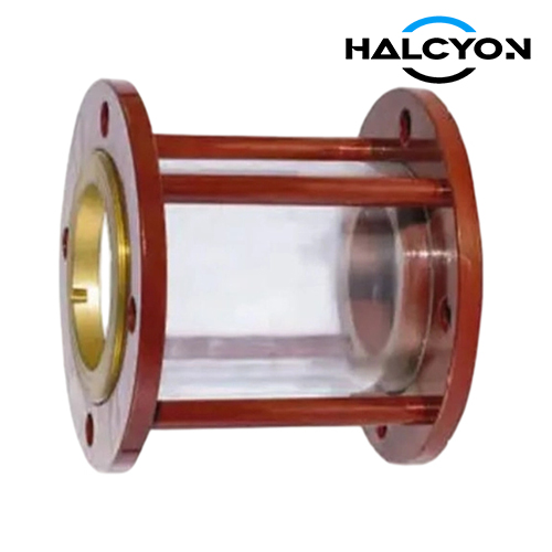
A Cast Iron Sight Glass is a rugged, economical in‑line flow observation device whose body and covers are manufactured from high‑grade grey or ductile cast iron. It houses one or two flat, circular toughened glass discs that provide a clear, distortion‑free view of the fluid flowing inside the pipe. The cast iron construction offers excellent vibration damping, high compressive strength, and a substantial cost advantage over steel or stainless steel alternatives. With a properly applied high‑build epoxy coating or hot‑dip galvanizing, a cast iron sight glass delivers decades of reliable service in seawater, freshwater, fuel oil, lubricating oil, bilge, and ballast lines. It is the most widely used sight glass material in general merchant ship and industrial applications where the combination of economy, strength, and durability is paramount.
Overview
1. Application
Cast Iron Sight Glasses are installed in a wide range of shipboard and industrial fluid systems where visual monitoring is required:
Fuel Oil Systems: On purifier outlets and engine inlets to confirm clean, bubble‑free fuel and to detect any water or sludge.
Lubricating Oil Systems: On main engine, auxiliary engine, and stern tube lube oil returns to verify flow and oil clarity.
Seawater and Freshwater Cooling: On pump discharges and heat exchanger outlets for immediate flow confirmation — often a class requirement.
Condensate and Boiler Feedwater: To monitor condensate clarity and detect oil contamination.
Bilge and Ballast Systems: To verify pump priming and discharge overboard through the oily water separator.
General Process Piping: In industrial plants for water, mild chemicals, and non‑aggressive liquid lines where cast iron is compatible.
2. Material Specifications
All materials are selected in accordance with ISO 12510 (or equivalent) and the service fluid:
Body & Covers:
Grey Cast Iron (EN‑GJL‑250, ASTM A48 Class 30, FC200): Economical and widely used for moderate pressures. Its excellent vibration‑damping properties are ideal for engine‑room piping.
Ductile Iron (EN‑GJS‑400‑15, ASTM A536 Grade 65‑45‑12, FCD400): Higher strength and toughness, specified for larger sizes and higher pressure ratings. Provides a greater safety margin.
Both grades are protected internally and externally by a high‑build, two‑component marine epoxy coating (minimum 250 µm DFT) or hot‑dip galvanizing to ISO 1461, providing long‑term resistance to the salt‑laden atmosphere.
Flat Glass Discs:
Borosilicate glass per ISO 3585 is standard. It offers high mechanical strength, excellent thermal shock resistance, and a safe operating temperature up to 280 °C. For low‑temperature services, toughened soda‑lime glass may be used. Every disc is edge‑ground, thermally pre‑stressed, and individually proof‑tested.
Sealing Gaskets:
EPDM for seawater and freshwater (up to 120 °C).
NBR for fuel oil and lubricating oil.
PTFE for higher temperatures and chemical compatibility.
Graphite or mica‑reinforced gaskets for steam and fire‑safe applications.
Fasteners: All cover bolts, nuts, and washers are stainless steel (AISI 316) to eliminate corrosion and ensure easy glass replacement.
3. Technical Specifications
Our Cast Iron Sight Glasses are designed, manufactured, and tested to the highest marine and industrial standards:
Design Standards: ISO 12510 (flat glass types), JIS F7212, CB/T 4224. Pressure–temperature ratings follow ASME B16.34 or EN 12516‑1 methodology.
Pressure Ratings: PN6, PN10, PN16, PN25 (ISO); Class 150, Class 300 (ASME); 5K, 10K, 16K (JIS). Higher ratings are available with ductile iron bodies.
Temperature Range: -10 °C to +280 °C with borosilicate glass and compatible gaskets. For continuous high‑temperature service, graphite gaskets are fitted.
Glass Configuration:
Single Flat Glass: For low‑risk, non‑hazardous fluids.
Double Flat Glass (Safety Design): Two independent discs. If the outer disc is accidentally damaged, the inner disc retains full system pressure. This is standard for flammable fuels and hot fluids.
Testing and Certification:
Every body is hydrostatically shell‑tested at 1.5 times the rated pressure.
The glass seating area is leak‑tested at full rated pressure.
Glass discs are individually proof‑tested to a safety factor consistent with the design code.
Full EN 10204 Type 3.1 material certificates are supplied for the body, glass, gaskets, and bolting.
Type approval or conformity certificates from all major IACS classification societies are available on request.
4. Dimension Specifications
Exacting dimensional control ensures direct interchangeability and straightforward installation:
Nominal Size Range: DN 15 to DN 200 (NPS ½" to 8"). Larger sizes can be engineered.
Flange Connection Standards: Flanges are drilled and faced to:
DIN EN 1092‑1 (PN6, PN10, PN16, PN25)
ASME B16.5 (Class 150, Class 300)
JIS B2220 (5K, 10K, 16K)
GB/T 2501 (PN6, PN10, PN16)
Flange facings are flat‑face or raised‑face to match the vessel’s piping specification.Face‑to‑Face Dimension: The body length between flange faces is manufactured precisely to the dimensions specified in ISO 12510, JIS F7212, or CB/T 4224. This ensures a bolt‑for‑bolt fit into an existing spool piece without any pipe modification.
Glass Viewing Diameter: The clear viewing area is optimized for each nominal pipe size, giving the largest possible view of the fluid while maintaining the required pressure‑bearing capability.
Tolerances: All critical machined dimensions — bolt circle, bolt hole diameter, gasket seating face, and glass retaining bore — are held to the strict tolerances of the applicable flange and sight glass standards.